Particle editing
Warning: This documentation is out of date and does not describe the behavior of the latest major version 4, which implements a new model. An up-to-date documentation can be found in the program help.
Abstract
It is possible to select any entity, manipulate their properties and memory, and get real time updates during a running simulation. For this purpose, editing windows can be pinned to particles. We will make use of this feature and experiment with an own example containing a structure building particle machine. We will then reprogram it by performing specific changes in the cell code and finally put several of them together to let them build something even more bizarre.
Pin editing windows to cells
We create a new simulation with the dimensions 1000 x 500 and set the friction and radiation strength to 0 and the rigidity value to 0.15. Then, we open the pattern editor and load the example /examples/patterns/builders/Spiral Builder.sim into our world.
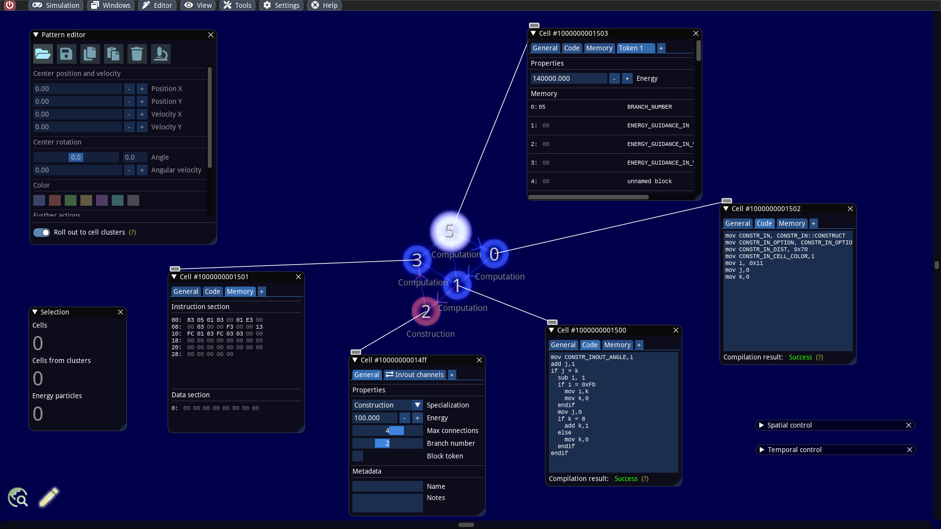
Our first goal is first to inspect the internals of the builder more detail. We zoom in, activate the information overlay, select all cells of the cell cluster and click the tool button with the microscope icon in the Pattern editor (or even faster: ALT + N). For each selected particle, a window is now pinned, which displays all internal properties and offers editing. We place the windows so that we can easily see the cells. In addition, the overlay information allows us to identify the so-called token branch numbers and cell specializations.
The cell that glows white possesses a token. By default, tokens always jump in the next time step to connected cells with the next higher token branch number with respect to a modulo arithmetic. But it is possible to bypass this mechanism and let the token jump to another cells. This trick is also used here and necessary, because the builder consists only of 5 cells and we have 6 different token branch numbers. We will discuss this in more detail in a later article.
The pinned windows are identical in structure and consist of several tabs:
General: Contains the properties common to each cell. Among other things, we can change the cell specialization here. In this example, we only use Computation and Construction functions. If the specialization is changed, the tabs may also change.
Code: This tab is only displayed for computation cells. It contains the source code that the cell executes when a token passes it. The code is written in an assembler-like language and consist of a maximum of 15 operations. It is translated into a machine language for the cells. If the source code is edited, it is immediately compiled and a feedback from the compiler is given under Compilation result.
Inside the code tab next to the compilation result there is a tooltip that gives an overview of the assembly language.
Memory: This tab is also only visible for computation cells. Here one can view and edit the memory contents of the cell with a hex editor. Each computation cell has 2 different memories: a fixed and a variable memory. The fixed memory is called instruction section and contains the translated source code. Each instruction is compiled into 3 bytes. The variable memory is called Data section and is the memory that can be accessed by the program itself.
In/out channels: This tab is visible for all non-computation cells and only gives general information about the input and output signals that are accessed from the token memory.
Token [1|2|3|...]: Cells can hold a certain number of tokens. Each token is displayed in an extra tab. In each tab the energy value and the memory of the corresponding token can be edited. The cell code of computation cells can also access this memory.
The token memory is represented in a special way as multiple hex editors arranged in a table. At the beginning of each row in the table one finds the address of the memory block, followed by the content (which can be edited) and the name(s) for this memory block, if available. Named memory blocks always have 1 byte length. It is also possible to define several names for one memory block. In this case all names are listed. The names of the memory blocks can be defined in the symbol editor and are used to be able to write more readable code for the computation cells.
In the above screenshot for example the memory address 5 possesses the names CONSTR_OUT, DIGESTION_OUT, MUSCLE_OUT, SCANNER_OUT and SENSOR_OUT and currently has the content 0x00.
Autotracking and live updates
A very helpful feature is that the pinned editing windows are maintained during a running simulation. One can then observe the changes of the contents in real time. The windows remain even when resetting to a snapshot. Only when the particles no longer exist, the corresponding pinned windows are hidden.
If you press ESC, all pinned windows will be closed, unless you are currently editing.
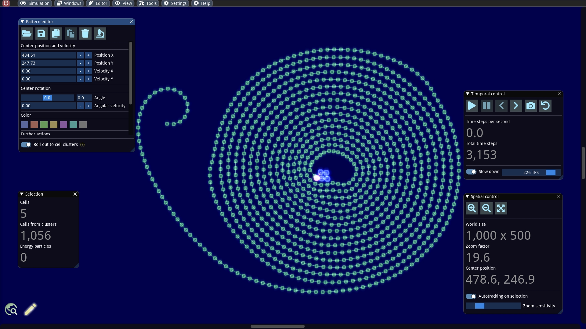
However, one usually has the problem that the inspected cells move out of the rendered area while the pinned windows are still visible. Manual navigation with the mouse is cumbersome and one can no longer concentrate on the content of the pinned windows. To solve this problem, one can enable the autotracking function in the Spatial control window. In this case, the visible area in the current zoom level is selected during simulation execution so that the selection is always centered.
So let us try this out: We activate Autotracking on selection, set a slow down of e.g. 3 time steps per second and start the simulation. Now one can observe well how the token jumps back and forth between the cells and how new cells are generated bit by bit. During the generation energy is consumed, which is provided in this example by the token (i.e. the token has a very large energy value initially).
Reprogram builder
As an example, we will make minimal changes to the cell code of the builder and observe the changes. Originally, the builder creates a red ribbon of connected cells that rolls up in a spiral. The red cell color of the new cells is set in the source code of the cell with the number 0 at line 4:
The colors are numbered from 0 to 6 and correspond to the order of the color selection in the Pattern editor. If a token passes this cell, the 4th line causes the color code for red (=1) to be written into the token memory byte named CONSTR_IN_CELL_COLOR. Later when the token passes the construction cell, it reads the token memory byte CONSTR_IN_CELL_COLOR, calculates modulo 7 and thus gets the corresponding color code for the new cell.
Now let us create a green ribbon for fun. For this we change the 4th line into:
We then obtain our desired result:
Combine several builders
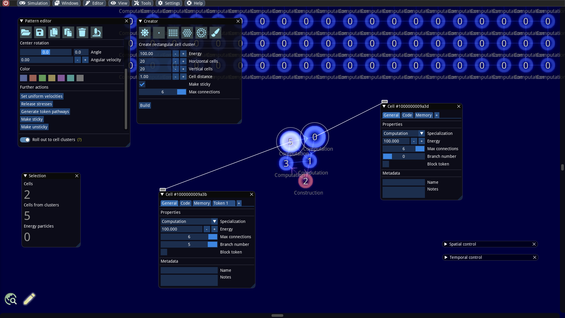
We will extend our example a bit more by plugging several builders together. To do this, we add a larger cluster, such as a rectangular 20 x 20 cluster to our world. We create it via the Creator window. It is important that we select the Make sticky option. With this option the created cells are still able to make new connections. By default all cells in this cluster are computation cells and have the token branch number 0.
As a next step, we also need to make parts of our builder sticky. Therefore, we select the cells numbered 0 and 5, as they will be glued to the rectangular cluster. We inspect these two cells and set the Max connections property to the maximum value of 6.
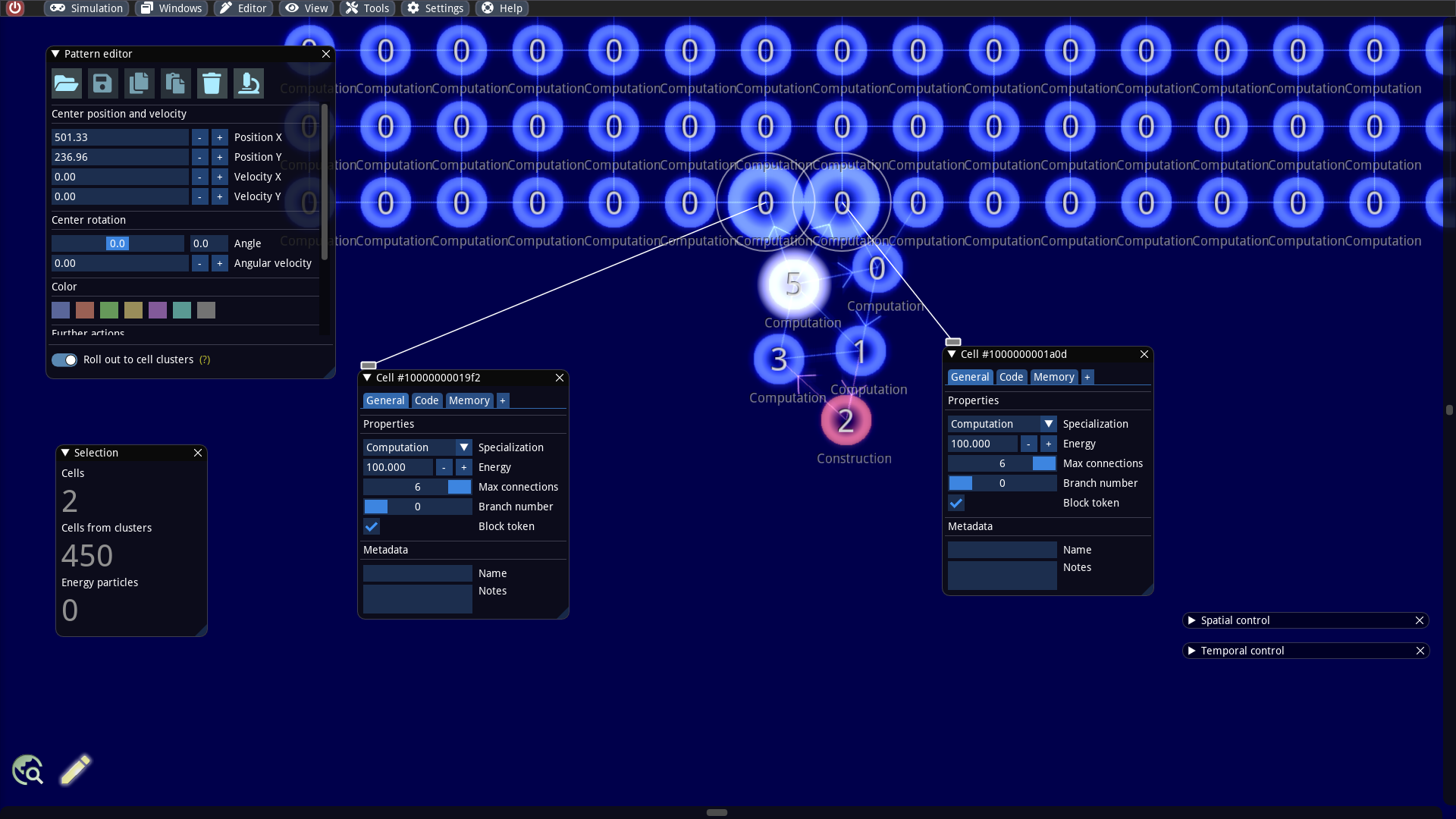
We select all 5 cells of the builder, keep the SHIFT key pressed and move the cells near the rectangular cell cluster. As soon as the distance falls below a critical threshold new connections are created automatically: The builder and the rectangular cluster are connected now! What remains to be done is to prevent the tokens from moving from the builder to the rectangle. This can be accomplished by selecting the connected cells on the side of the rectangle, inspect them and activate the flag Block token (see screenshot below). This flag causes that the cell cannot accept tokens anymore.
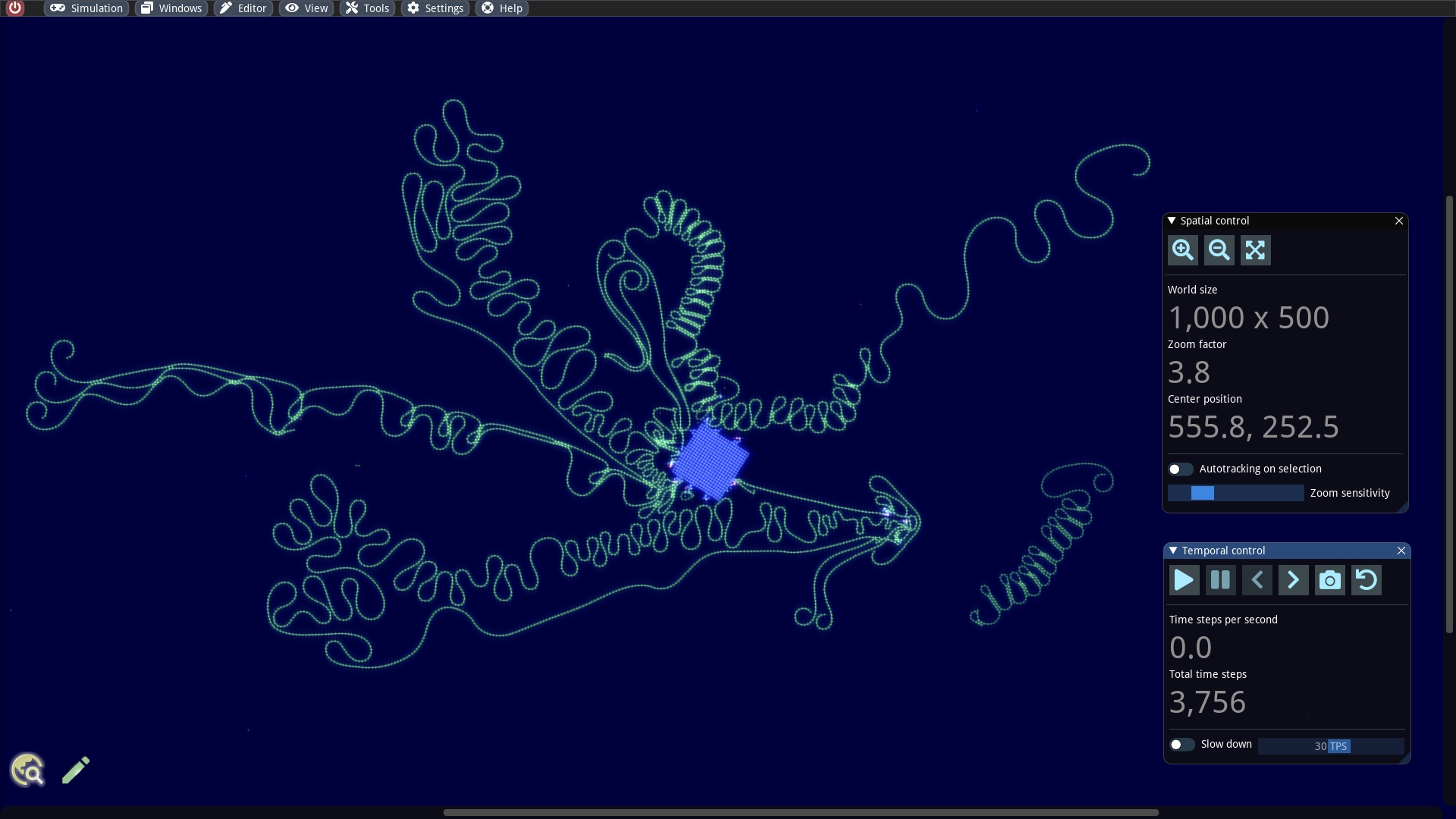
To make the simulation a bit more interesting and to deepen our cell editing practice, we repeat the whole thing and attach more builders to the rectangle, e.g. also to other sides. Our strange construction could then look like this, for example:
We are curious and can now execute the simulation. The created construction looks somewhat similar to a protein. It is worth trying different settings for the simulation parameters. For example, one can play around with the value for rigidity.
Last updated