Simple swarmbot
Warning: This documentation is out of date and does not describe the behavior of the latest major version 4, which implements a new model. An up-to-date documentation can be found in the program help.
Abstract
Cells in ALIEN can perform a wide variety of actions. We will address cell programs, mass sensors and motion control in this section. These functions will be explained by building a simple swarm robot that scans its environment for particle concentrations with a specific color and moves in that direction.
Cell skeleton
The basic idea is that our swarmbot scans its environment for certain particle concentrations and as soon as it finds something, it heads for the target. If the target is on the left side, a forward movement combined with a left turn should take place and in the other case a right turn.
A simple skeleton for our purpose consists of a loop-shaped structure in which a token can circulate. In this structure, we need a muscle on both sides that provides us with an impulse depending on the direction we want to direct. We also need to accommodate a sensor that will give us the distance and angle where particle concentrations with a certain color are located.
The above structure is composed of 7 cells and consists of 3 functional units:
The 2 cells on the left side are used to generate an impulse to steer to the right. One of these cells is a computational cell and is used to control the muscle cells. A muscle cell can only generate an impulse in the direction or opposite direction from which the token originates.
We still need a similar unit on the right side. A forward impulse on the right side leads to a left steering of the total structure.
In front of the swarmbot is our visual unit. It consists of a computational cell and a mass sensor.
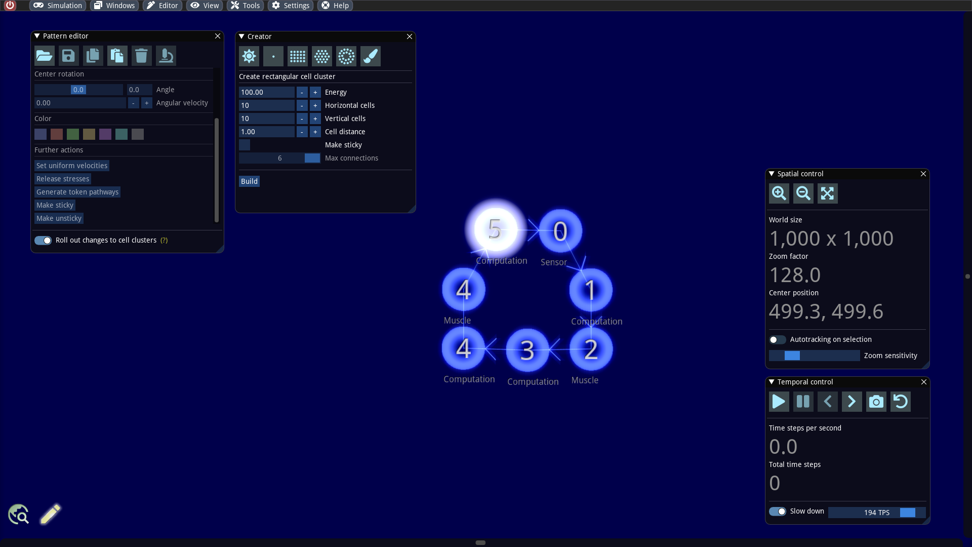
We now construct the basic structure in the editor by creating 7 cells and connecting them individually. Because there are only 6 different token branch numbers, it is not possible to reproduce a directed cycle. Here we will help later with a special cell program. Furthermore, we create a token at an arbitrary cell. To this end, we inspect one of these cells in the pattern editor (shortcut ALT+N) and click on the tab with the plus symbol.
We set the cell specializations (Computation, Muscle and Sensor) and token branch numbers as indicated in the screenshot above. The different cell types used here will be explained in more detail in the following sections and then an appropriate implementation for our machine will be presented.
Working principle of a computing cell
A computing cell has two memories: One memory in which instructions are encoded and a data memory. As soon as a token enters such a cell, its instructions are executed. The instructions have access to the data memory of the cell as well as to the data memory of the token. Basically, a cell program can consist of a maximum of 15 instructions. Each instruction is represented as 3 bytes in the memory. The data memory of a cell contains 8 bytes while the memory of a token contains 256 bytes. ALIEN provides a built-in compiler that allows the user to write the code in an assembler-like language. The following instructions are supported:
In C syntax, for example, the statement at line 1 would read as op1 = op2; and at line 2 op1 += op2;. op1 should point to a particular byte in memory, while op2 can be a memory byte or a constant (8 bits size). There are several ways to reference a memory byte for op1 or op2:
Direct reference to a token memory byte: In this case a byte in the token memory is referenced via an 8 bit address. The address can be specified as decimal or hexadecimal value. Syntax (example):
[32]or[0x20]Direct reference to a cell memory byte: A memory byte of the cell can also be referenced. Syntax (example):
(0)Indirect reference to a token memory byte: It is also possible to obtain the address itself from memory when referencing a token memory byte. Syntax (example):
[[32]]or[[0x20]]In this case the actual address is obtained from[0x20]and then used to reference the corresponding memory byte.
To make writing code easier, there is a symbol table where one can specify aliases for constants and references to memory bytes. For instance, a code like
is much easier to understand than the decompiled machine code
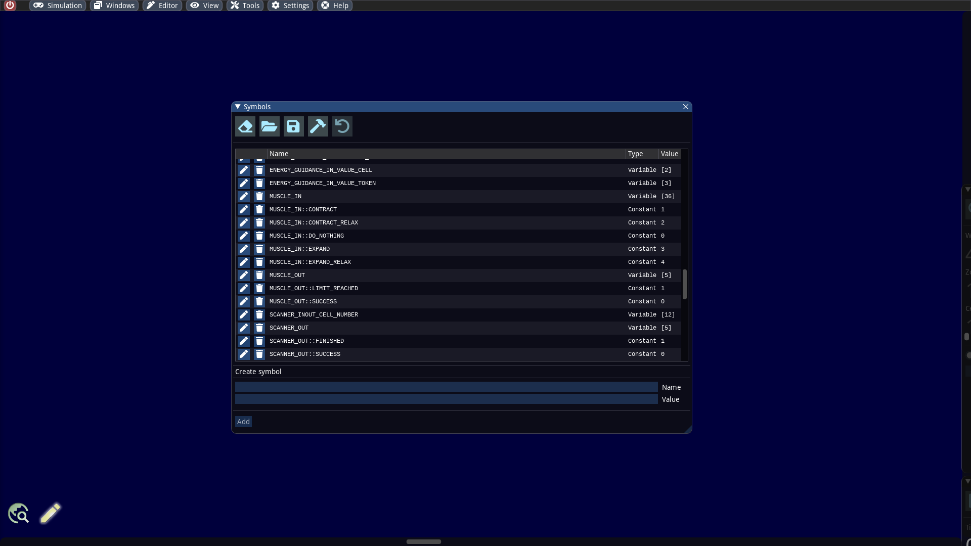
The symbols can be viewed in the Symbols window reachable via the Editor menu. Some of the memory bytes are used to control other cell functions. There are many predefined symbols for this purpose.
Working principle of a muscle cell
Muscle cells can perform four different operations. The reference distance of the muscle cell to the predecessor cell is changed and, if necessary, an impulse is generated at the same time. The predecessor cell designates the cell from which the token originates that has just entered the muscle cell.
The graphic above illustrates the different operations. Here we have two connected cells (a computing cell on the left and a muscle cell on the right) and a token that jumps from the left to the right cell and thus triggers the muscle function.
The first operation refers to a pure contraction. Here, the reference distance of the cell connections is reduced by a fixed factor. This results in a force that brings the cells closer together.
In the second case, the reference distance is also reduced and at the same time the muscle cell is given a forward impulse.
The third operation describes a pure expansion. The distance between the connected cells is increased.
Analogous to the second case, the fourth operation leads to an increase in distance and, at the same time, to a backward impulse of the muscle cell.
The indication of which operation should be performed is specified in the token memory. To simplify programming, there are default symbols for the memory location and its values. These can be viewed in the symbol editor, which can be opened in the editor menu.
The symbol MUSCLE_IN denotes the memory byte in the token where the muscle cell reads the operation to be performed. It is an alias for the memory byte at position 36, which can also be written as [36] in the code. The different operations, on the other hand, are encoded via the symbols MUSCLE_IN::CONTRACT_RELAX, MUSCLE_IN::CONTRACT, MUSCLE_IN::EXPAND_RELAX, MUSCLE_IN::EXPAND in the above order. These simply refer to constant values.
For example, if we want the muscle cell to perform a contraction, we must set the appropriate value in the token memory beforehand. The following command in a preceding computing cell we do this:
Working principle of a sensor cell
A cell with a sensor is able to detect particle concentrations with a certain minimum density and a certain color in the vicinity. It will return the relative distance and relative angle of the found target. If there are multiple targets, the one with the smallest distance is considered. Let us illustrate its working with a simple example.
To understand its functionality, we consider the cell of the sensor and the predecessor cell of the token. In the graphic above we see in the center a sensor cell to which a token jumps from a cell connected on the left. From the relative position of both cells we can define what means front and back. In the case above, e.g., the direction to the right (sensor line) is specified as the front.
We now assume that we want to search for nearby green particle accumulations. In our illustration, three colored clusters can be seen. The cluster with the smallest distance is yellow and then two green ones follow. Our sensor would detect the middle one and would measure the relative distance d and the relative angle α from that cluster. The sign of the angle gives us the information whether the target is above or below the sensor line. Since the determined target in our case is below the sensor line (red shaded area), the angle is positive.
Implementation of a sensor control
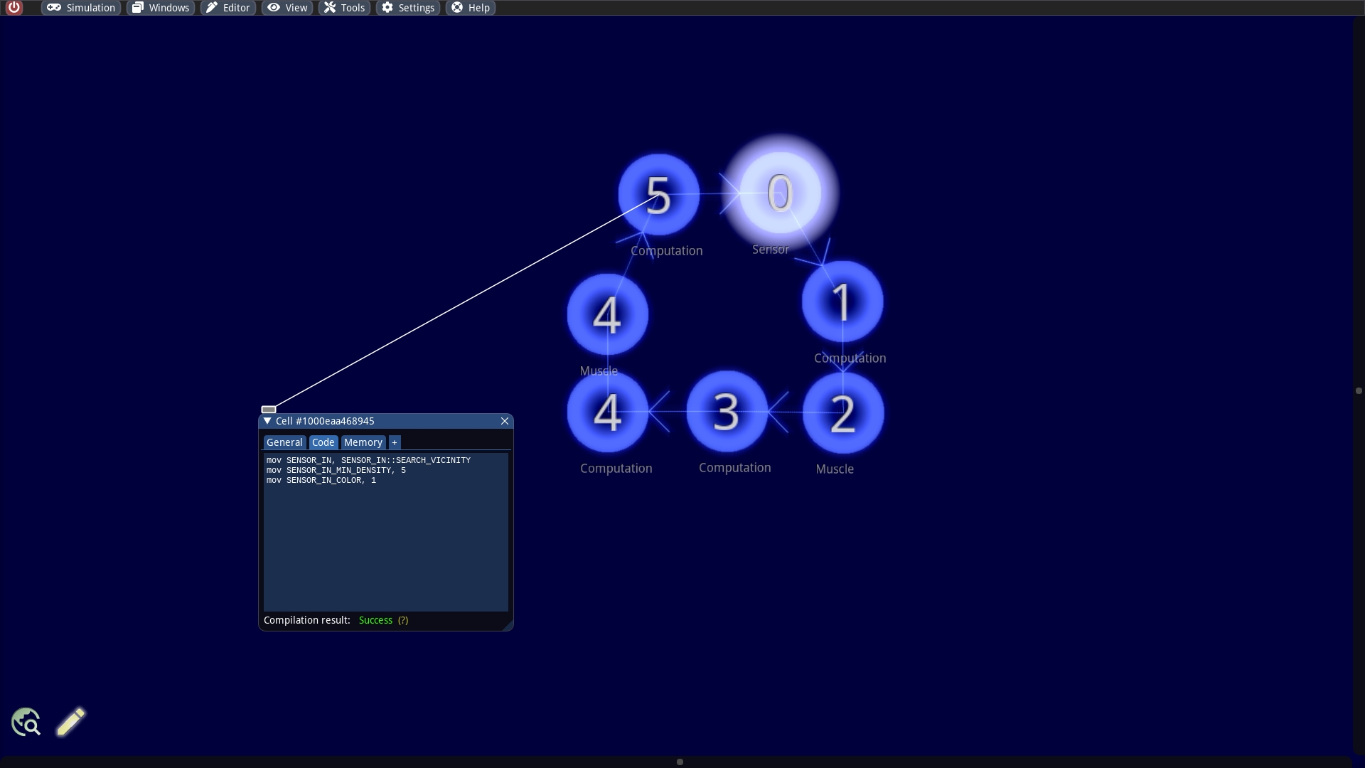
In the following we will focus on the concrete implementation. The sensor cell of our swarmbot has an preceding computing cell that controls it. We only need to set a few options that provide the needed information for the sensor. For this purpose we can place the following small program in the upper left computing cell.
The code reads as:
At line 1 we specify the working mode. A sensor knows two different working modes, which are defined in the memory byte SENSOR_IN:
The scanning of the entire vicinity, which is indicated by the value
SENSOR_IN::SEARCH_VICINITY.If we want to scan only in a particular direction it is necessary to set the value
SENSOR_IN::SEARCH_BY_ANGLE.
At line 2 we specify the sensitivity of the sensor. The memory byte SENSOR_IN_MIN_DENSITY contains the minimum mass density of particle accumulations that the sensor would detect as potential targets. The density value indicates the number of particles in an area with size 8 x 8.
Finally, we provide a particle color at line 3. A value between 0 to 6 is expected here. The value 1 corresponds to the red color.
When the sensor function has been executed, we can retrieve the result in SENSOR_OUT whether a target has been found or not. If this is the case, it has the value SENSOR_OUT::CLUSTER_FOUND (see code from the muscle control). We obtain the angle of the target in SENSOR_INOUT_ANGLE, the distance in SENSOR_OUT_DISTANCE and the exact density in SENSOR_OUT_MASS. It should be noted that all these information are encoded in one byte each. For the specification of the angle, 0° to +180° correspond to the byte values from 0 to 127 and -180° to 0° correspond to the byte values from 128 to 255.
If there is a compile error with the code, it may be because the correct symbols were not loaded. In this case, the default symbols, which can be restored in the editor, are sufficient.
Implementation of a muscle control
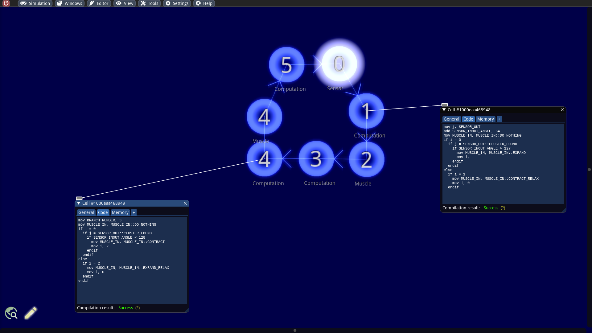
To control the muscles for our swarmbot, we need the following cell programs:
Let us have a closer look at the cell program on the right side first:
Line 1: The memory byte which contains the return value from the sensor is stored in another memory byte with the symbol
j. This is necessary because different cell functions sometimes use the same memory byte as output.Line 2: An angle correction of the sensor data is performed here. The instruction calculates the relative angle of our target if we would rotate our frame of reference by 90° counterclockwise (a value of 64 is interpreted as 90° in our encoding). It corresponds to the reference frame where the muscle cells are controlled.
Line 3: As default, we instruct the muscle cell to do nothing.
Line 4: It is checked whether the memory byte
iis equal to0. This is the case if no muscle operations were performed in the last cycle.Line 5: It is then checked whether the sensor has found some target.
Line 6: The angle of the target is returned as a signed byte. A value greater than 127 therefore represents a negative angle and means that the target is on the left side.
Line 7: The muscle cell on the right hand side is instructed to perform an expansion together with a backward impulse, which will cause the swarmbot to turn left.
Line 8: The memory byte
iis set to1to perform a contraction in the next cycle.Line 12: It is checked if an expansion was instructed in the last cycle.
Line 13: In order for the cell connection to regain its original reference distance, a contraction without an additional impulse is now instructed.
Line 14: The original state for the muscle is restored, which is
i = 0.
One can see in the code that an endif is missing. It can be omitted at the end of a program. This is even necessary here, because a cell program can only consist of a maximum of 15 commands.
The program of the computing cell on the left side is the counterpart to the one of the right side with the difference that here a forward impulse must be generated to initiate a clockwise rotation. This is due to the fact that the token reaches the muscle cell from below while in the right side it reaches the muscle cell from above (i.e. the frame of reference is rotated by 180°).
Line 1: Here, a new branch number is assigned to the token. Normally the token obtains the branch number from the underlying cell. However, in our case we want the token to jump from the cell with the number 4 to the connected cell above with the same number. Since tokens always jump to the cells with the next higher number, we have to set the branch number of the token to 3.
Line 2 - 15: The code works similarly as the previous one with the difference that we first perform a contraction and then an expansion. Since this results in a right turn, this operation is only performed when the sensor has found a target on the right side.
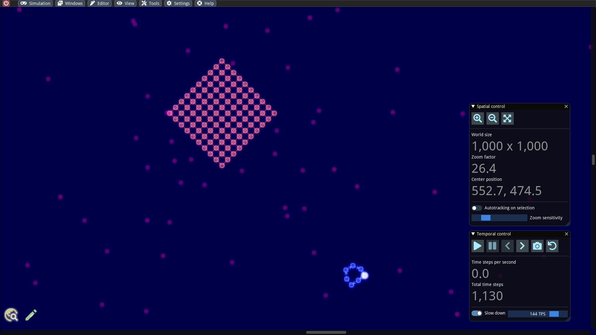
Testing the result
We have now finished putting together our machine. One can also find it as a pattern file at ./examples/patterns/swarmbots/Interceptor (Red Target).sim if something does not work as expected. To experiment with our creature, we can, for example, build a large red rectangular cluster of cells nearby. We should then observe how the red cluster is pursued or orbited by the swarmbot while running the simulation (with a slow down!)
Last updated